
DiscoverCars.com

Wednesday, February 16, 2022

A closer look at minimizing charging losses: The charger (Part 2)


In the previous article, we looked at the various losses incurred on the AC side of the circuit while charging an EV’s battery (from the breaker in the load center to the EVSE inlet on the EV), as well as things that could be done to minimize them, either by the OEM, the electrical contractor or the EV owner. This time our focus will shift over to the DC side of the circuit (and more specifically, the charger itself). 

Regardless of where the charger is actually located—either onboard the EV or within a curbside DC fast charging station—a few basic functional requirements will be common to all chargers: provide galvanic isolation between the AC mains and the EV (i.e. have a transformer for isolation somewhere in the circuit); regulate and/or limit the current and voltage to the battery (i.e. be capable of constant current [CC] or constant voltage [CV] operation); and, more than likely, ensure the current waveform drawn from the mains is aligned in time and magnitude with the voltage waveform (in other words, perform power factor correction, or PFC). Unsurprisingly, there are numerous potential solutions to performing all three functions, but for the sake of not turning this article into a proverbial “Homeric catalog of ships,” we’ll just concentrate on the most common configurations—ignoring, for example, the use of a mains-frequency transformer for isolation, or so-called “single-stage” PFC and isolation converter topologies (which inevitably perform no function terribly well).

Basic requirements common to all chargers include: provide galvanic isolation between the AC mains and the EV; regulate the current and voltage to the battery; and perform power factor correction.

Assuming that isolation will be done with a high-frequency transformer, rather than a mains-frequency one, the first stage of the DC charger is the mains-frequency rectifier. For chargers that also do PFC—pretty much all of them these days—a bridge rectifier with a very small amount of filter capacitance (strictly to reduce noise and transients from the mains) will be used to produce sinusoidally-pulsating DC with a ripple frequency that is twice the mains frequency (i.e. 120 Hz for 60 Hz mains) and a peak value that is approximately 1.4x the RMS value of the mains voltage (~165 VDC for 120 VAC mains, or ~330 VDC for 240 VAC). The following PFC stage will then convert that pulsating DC to a much more smoothed-out DC with an average value close to 400 VDC, typically using a boost converter. Since the same DC bus voltage is produced regardless of the AC mains input voltage, this configuration is commonly described as universal input—meaning that the onboard charger can be plugged into either a 120 VAC or 240 VAC outlet without any action or concern on the part of the user to ensure things don’t blow up. Finally, there are the transformer isolation and CC/CV regulation functions, which are usually performed by a single converter. The most common converter topology used here is a full-bridge converter operating at a switching frequency of >50 kHz (typically in the range of 100 kHz-300 kHz, to be more precise) driving a high-frequency transformer. Control of the output current and/or voltage can be achieved by the conventional method of varying the duty cycle of each complementary pair of bridge switches from 0% to 50% (i.e. pulse-width modulation, or PWM), or through more exotic methods, like varying the phase shift of each pair from 0° to 180° (i.e. phase-shift modulation).


Series resonant full bridge converter:
(a) The topology of DBSRC; (b) The equivalent circuit of DBSRC.

Rectifying the AC from the mains into DC is usually done with four conventional silicon junction diodes in the bridge configuration. This puts two diodes in series with the mains at all times, and since every diode introduces a voltage drop while conducting (aka its forward voltage drop, or Vf), the humble bridge rectifier can exact a surprisingly large toll on overall charger efficiency. Diode Vf typically has a minimum value of 0.4 V to 1.8 V (depending on diode type and peak inverse voltage [PIV] rating) which also increases with current, both from simple (ohmic) resistance and a logarithmic factor of, typically, 60 mV/decade of current (also depending on diode type). Generally speaking, the faster a diode switches from conducting to blocking (i.e. its reverse recovery time, or trr) and the higher the PIV rating, the higher the initial Vf will be. Diodes operating at mains voltages and frequencies don’t need to be terribly fast, so a conventional Si pn junction type can be used with a trr of a few microseconds, but one shouldn’t be too stingy with the PIV, as the mains are a harsh place, filled with voltage spikes and transients—typically a 600 V PIV rating is the bare minimum for reasonable survivability, but there’s often little increase in Vf when going from 600 V to 1.0 kV or even 1.2 kV. With this combination of diode type and ratings, the Vf will likely end up at around 1.0 V at nominal rated current, so we’ll see a total drop of 2.0 V in the bridge rectifier. That’s a 1.7 percentage-point hit to efficiency at 120 VAC input right there! Some improvement can be had by going with a much higher current rating than is necessary—lowering ohmic and logarithmic losses—but getting to the mythical 0.6 V drop of a Si-junction diode at zero current ain’t happenin’.

Some improvement can be had by going with a much higher current rating than is necessary—lowering ohmic and logarithmic losses—but getting to the mythical 0.6 V drop of a Si-junction diode at zero current ain’t happenin’.

The next stage in the charger performs power factor correction, and this is usually done with a boost converter. In the boost topology, energy is stored in a choke when the switch is on, then some or all of that energy is released to the output capacitor via a blocking diode when the switch is off. It might seem counterintuitive, but at high power levels it is common to retain some energy in the choke from cycle to cycle (this is called continuous conduction mode, or CCM), because the peak and peak-to-peak (i.e. AC) currents are much lower than if the choke completely empties each cycle (called, unsurprisingly, discontinuous conduction mode, or DCM). In fact, the peak current in any of the power stage components when operating in DCM will be twice the average current, minimum, because current starts from zero every cycle. This not only exacerbates I2R losses throughout the power stage, it also incurs more AC losses in the choke, as they tend to be exponentially proportional to the peak-to-peak swing. However, the one huge disadvantage of CCM operation is that the blocking diode has to instantaneously switch from conducting forward current to blocking reverse current (it needs a trr of zero, in other words), which would normally mean using a Schottky type. Before the commercialization of SiC Schottky diodes, that was a non-starter, since the PIV rating of Si Schottkys tops out around 100 V, but SiC Schottkys have PIV ratings of 600 V and above, so they are the diode of choice here. They do have a higher Vf than their Si-junction counterparts (typically >1.8 V), but this has far less of an impact on overall efficiency than in the bridge rectifier, because there is only one of them in series with the relatively high voltage output (e.g. 400/401.8 = 99.55%). The other main points of optimization are the choke and the boost switch. In CCM operation, AC losses in the core and windings of the choke are less of a concern, so the focus should be on minimizing the DC (I2R) losses of the windings themselves (the converse is true for DCM—minimizing the AC losses then takes priority). For the switch, the obvious parameter to optimize is the on-resistance (RDS[ON]), but the less-obvious—and perhaps more important—parameter is the output capacitance (COSS), because this capacitance is charged up to the output voltage value every time the switch turns off, only to be discharged across the switch at next turn-on. This is an example of a loss that is both frequency- and voltage-dependent, and one that will covered in more detail next.
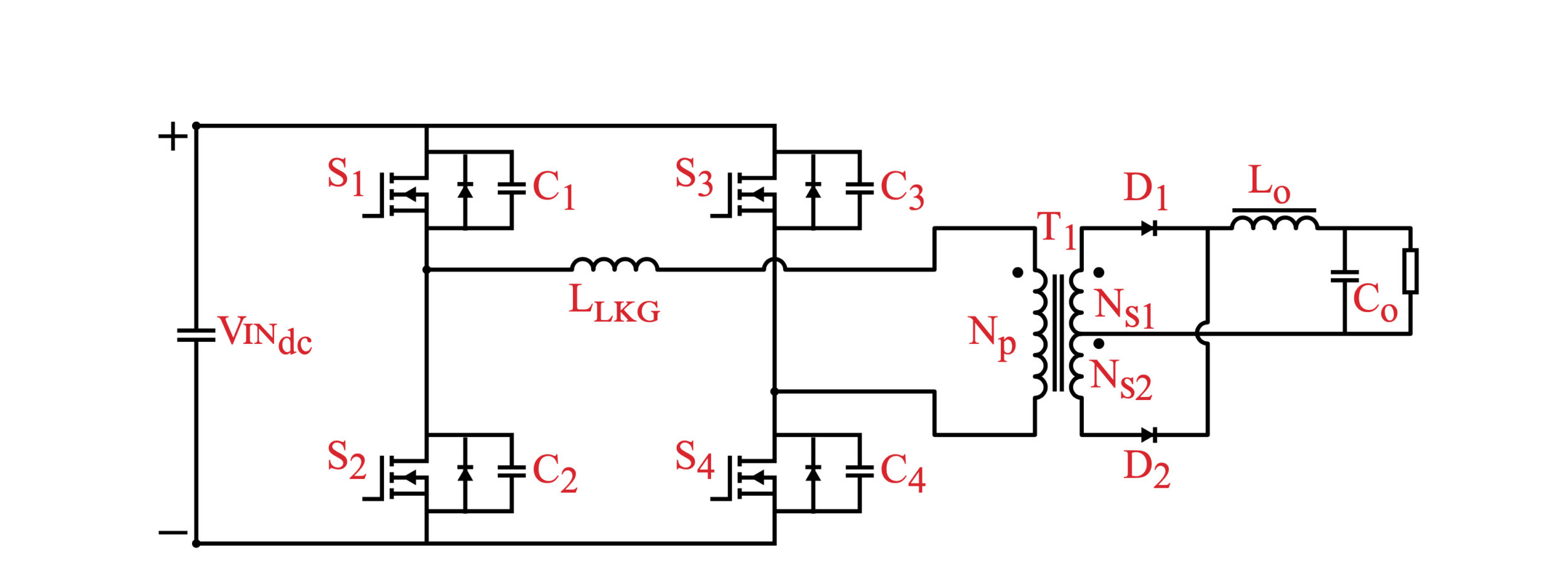
Phase-shifted full bridge converter

The final stage in the charger is usually a full-bridge converter which drives an isolation transformer, followed by a full-wave rectifier (with a choke-input filter if PWM is used to achieve CC/CV regulation). As with any switchmode converter, the higher the switching frequency, the smaller the magnetic and energy storage elements (transformers, chokes and capacitors), but, as was just hinted at above, increasing the switching frequency without bound is, well, bound to cause problems. In fact, switching losses routinely dominate in traditional “hard-switched” bridge converters above a switching frequency of 100 kHz or so, and the main contributors are the aforementioned charging/discharging of COSS, along with overlap of voltage and current during the transitions. A number of solutions for reducing—or even eliminating—switching losses are possible, with varying tradeoffs between reliability, complexity and flexibility (of, more specifically, the load range that can be accommodated while maintaining lossless switching), but broadly speaking, they fall into two categories: fully resonant and resonant transition (aka quasi-resonant).

Fully resonant converter topologies use resonant LC networks (aka tanks) to shape either the current, the voltage, or both waveforms into sinusoids.

Fully resonant converter topologies use resonant LC networks (aka tanks) to shape either the current, the voltage, or both waveforms into sinusoids so that the switches can be turned on (or off) at the moment the voltage (or current) passes through zero. This eliminates switching loss from overlapping voltage and current (if one parameter is zero, then the product of both is zero, of course), but the disadvantages of resonant converters are steep enough that they are infrequently used these days, because: (1) the resonant tank requires a certain amount of energy sloshing back and forth between its inductor and capacitor to function, either requiring a high minimum load or exhibiting terrible light-load efficiency; (2) this circulating current in the resonant tank incurs additional ohmic (I2R) losses from the various resistances in its path; (3) the only way to vary output power is by changing either the switching frequency or the pulse repetition rate, making compliance with EMI/RFI regulations more difficult; (4) when varying the frequency to effect regulation of the output, inadvertently crossing over the resonant peak will invert the control function, causing the output to collapse and, most likely, destroying the switches; (5) finally, the resonant frequency is dependent on the precise values of inductance and capacitance in the tank, and these are notoriously difficult to control in production volumes, possibly requiring hand-tuning of each unit.

The main solution to the downsides of fully resonant operation is to confine the resonant period to just the switching transitions, and one of the most popular ways to do this is to take advantage of the ringing that naturally occurs between the lumped sum of COSS from each switch in a bridge with the leakage inductance of the transformer. In hard-switched bridge converters, this ringing is a huge nuisance that requires dissipative snubbers (RC networks across each switch) to dampen it out so as to prevent failing EMI/RFI requirements. One of the most popular quasi-resonant topologies that uses the ringing between COSS and Lleakage is the phase-shifted full-bridge, and while discussing it in detail is beyond the scope of this article, those who are interested can look up Texas Instruments application note SLUA107A for more information. Regardless of the specific quasi-resonant technique employed, the current and voltage waveforms during the power transfer portion of each switching period will still be square—the same as in conventional hard-switched PWM—so peak currents and voltages will be the same as their hard-switched counterparts. Finally, because many quasi-resonant techniques utilize parasitic circuit elements for their operation, they can relax the need to minimize the leakage inductance of the transformer or the COSS of the switches, which usually translates into a lower cost for each of these often-pricey components.

Finally there are “wireless” chargers, which transmit power across an air gap from a coil in a base station to one in the EV. These chargers can be extremely convenient to use, but rarely exceed 80% transfer efficiency, and that’s before the other losses outlined above are factored in. Still, they seem to be gaining in popularity despite that, so they will be the topic of a future article. In the meantime, choosing SiC MOSFETs and a resonant transition converter topology for the charger are the two best ways to maximize its efficiency.  

This article appeared in Issue 58 – Nov/Dec 2021 – Subscribe now.


from Charged EVs https://ift.tt/paBeFUq

Pressure mapping insights improve battery life and performance


Sponsored by Tekscan

Battery manufacturers and their stakeholders strive to design batteries that are smaller, safer, and longer-lasting. The Electric Vehicle market in particular is invested in tools and technology that can help quantify and closely examine battery dynamics. Pressure mapping plays a critical role in this type of research & development, lifecycle testing, durability testing, and quality control. 

Many familiar with the construction of a lithium ion battery will say that it “breathes.” However, few methods exist to quantify the internal stress this activity may have on battery life and performance. Charging and discharging causes changes in temperature, electrochemistry, and the mechanics of the internal components, caused by changes in pressure. Even between relatively flat surfaces, one finds the interface pressure distribution is often not uniform within localized areas of peak pressure. Pressure mapping technology like Tekscan’s I-Scan System helps design engineers obtain insights into areas that may impact design and quality. 

Significant internal pressures have been shown to cause plastic deformation, delamination, and increases in internal impedance. Lower stack pressures tend to yield better long-term performance, but when pressures are too low, delamination may still occur. Designers are challenged to find the “sweet spot” for housing pressure, and pressure mapping technology is an optimal solution for battery design and testing due to the thinness and flexibility of the sensors, and the ability of the accompanying software to map pressure changes over time.  This video shows an example:

Solid state batteries are a promising advancement for the electric vehicle market because their composition makes them less volatile and less vulnerable to fire than liquid li-ion batteries, and they have the potential for higher energy density. However, their inherent properties pose some challenges. The rigid electrolyte generates a non-uniform pressure distribution, and concentrated pressures can lead to cracking in the material, reducing their efficiency. Pressure mapping can reveal hot spots and help engineers make informed design decisions aimed at preserving battery life.

Sponsored by Tekscan


from Charged EVs https://ift.tt/A8EnXxl

Uber drivers get Wallbox charging stations at a discounted price


Following a pilot program, Uber and Wallbox are expanding their partnership nationwide. The partnership offers a discounted package to Uber drivers that includes a Wallbox Pulsar Plus charger, along with installation and financing options.

The EV charging package will be rolled out in four geographical groups, and is scheduled to reach nationwide coverage (excluding Alaska) by the end of April. The two companies are also discussing a global rollout of the program, beginning in Europe and Canada.

Uber also offers drivers of EVs a Zero Emissions incentive that pays them an extra $1 on every Uber trip (up to $4,000 annually).

“Expanding this pilot program across the US is a natural next step as we work together to build more sustainable transportation,” said Douglas Alfaro, General Manager of Wallbox North America. “Our charger plus installation package has simplified EV usage for Uber drivers in the Bay Area, and we are thrilled to be able to offer the same support to drivers all over the country.”

“Helping drivers go electric is a crucial part of our plan to get to zero-emissions by 2030 in the US,” said Andrew Macdonald, Uber’s Senior VP of Mobility and Business Operations. “This partnership with Wallbox helps drivers by making it more affordable and accessible to charge their EVs.”

Source: Wallbox Chargers


from Charged EVs https://ift.tt/HCyijFY

Infinitum Electric brings its PCB stator technology to EV motors


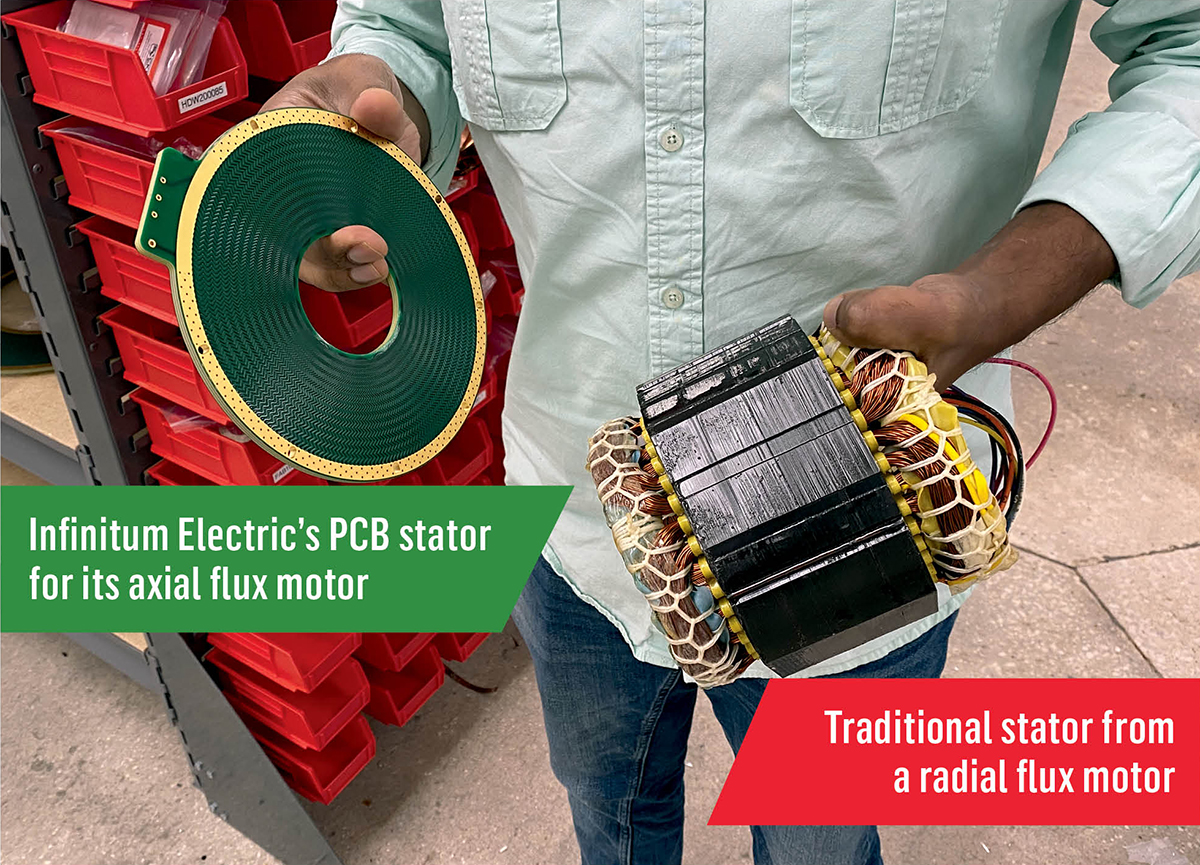
Infinitum Electric says its axial flux motors with printed circuit board stators offer weight reduction, cost reduction and efficiency gains.

Batteries are getting a lot of media coverage these days—they represent a rapidly-developing technology that’s seen as the key to the electrification of transport. Motors, however, are considered a fairly mature technology, and the humble rotor and stator seldom get to be in the spotlight.

Texas-based Infinitum Electric aims to change that. The company’s bold red motors demand attention for their design and performance.

Infinitum Electric says its unique motor design—an axial flux architecture that uses a printed circuit board (PCB) stator—dramatically reduces size and weight, improves efficiency and reliability, and also offers high speed, excellent torque, quieter operation and a modular platform.

Charged recently spoke with Infinitum VP of Business Development Bhavnesh Patel to catch up on what the company is doing, and get a more detailed explanation of what makes Infinitum’s motors different.

Charged: Could you explain the advantages of using a PCB stator? Is it suitable for EV applications? 

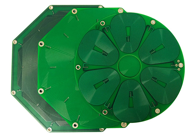
Bhavnesh Patel: Every motor or generator has a stator. It typically consists of heavy iron with copper wire wrapped around it. We etch the copper onto a PCB to replace that iron-copper stator. Our motor is equal in performance to a conventional motor with a third less copper and absolutely zero iron. This results in a much smaller, lighter electric motor. 

We etch the copper onto a PCB to replace that iron-copper stator. 

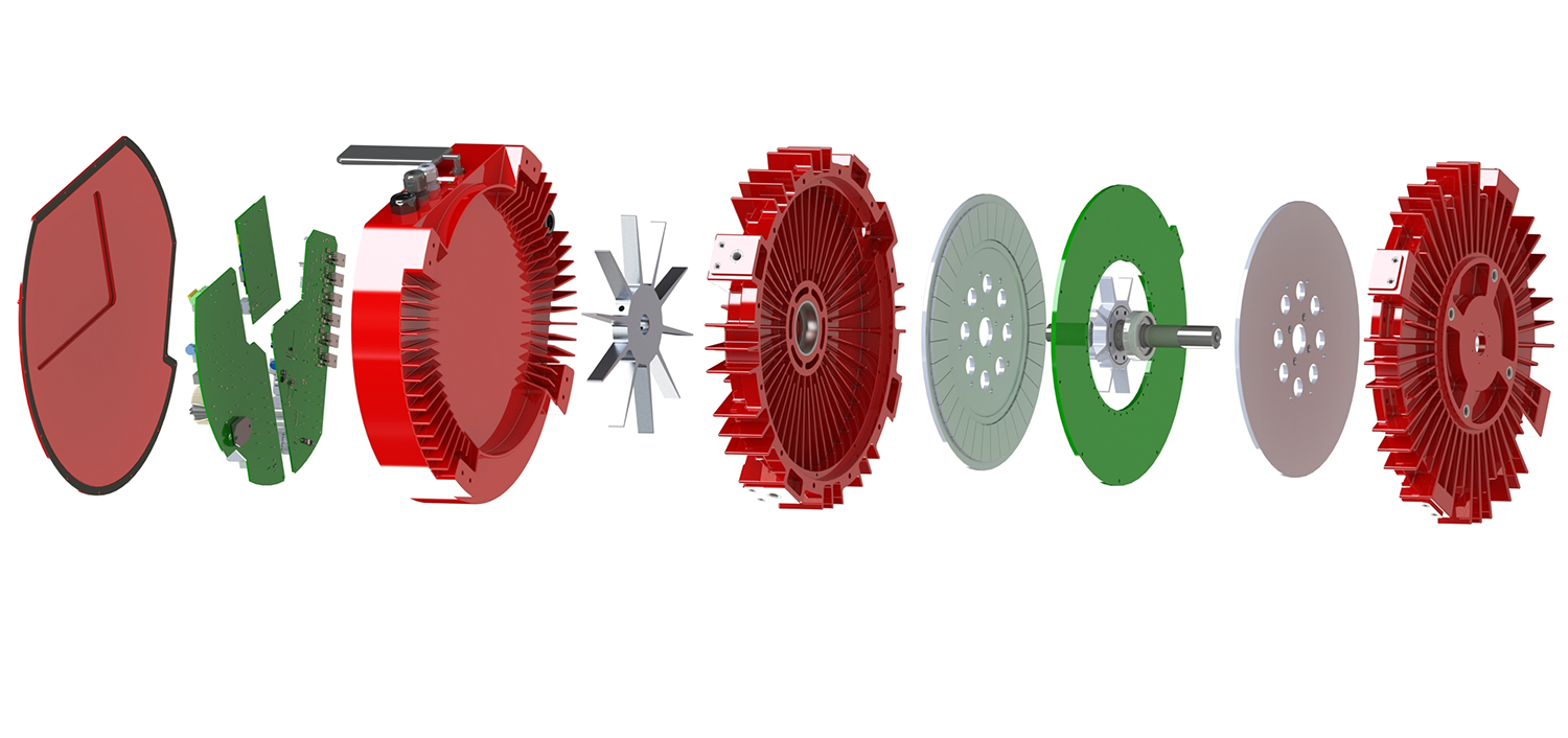
A traditional cylindrical motor type is a radial flux motor. Our equivalent is an axial flux motor, which has a much thinner form factor and is a lot simpler to put together. You have a rotor on the bottom, a rotor on the top and then your stator sits in the middle. What we do for our traction motor is stack a couple of these together. We have a 150-kilowatt machine that we’re working on right now. It’s a very modular approach—if we have a customer that says, “Hey, I need 200 kilowatts or 300 kilowatts,” we stack multiple modules together. Beyond the modularity, we have a very significant power density advantage, meaning that for the amount of mass we have, we can put a lot more power through it. And we ultimately make the vehicle a lot lighter and more efficient.

Charged: Why do you stack modules? 

Bhavnesh Patel: There are a couple of reasons why we choose to stack it. One is that, with an axial flux technology, as the torque in the application goes up, the diameter increases. In order to constrain the diameter, we can stack multiple modules. We could do a 100-kilowatt motor with one stator—it would just be wider. For a passenger vehicle, for example, that might not be feasible, but a truck application absolutely could be feasible. It depends on the application. We’ve stacked modules, we’ve done single-stator—both are very feasible.

Charged: How do you achieve a third less copper usage?

Bhavnesh Patel: The surface ratio of a PCB stator vs a copper wire-wound stator is greater, which allows for more effective cooling. Thermal dissipation is the constraint in running additional current through copper. A larger surface ratio allows for higher thermal dissipation and as such, less copper is required. This is a fundamental physical property. In a conventional liquid-cooled traction motor, two approaches are typically utilized—a water jacket integrated into the motor housing, which cools the iron stator and fluid across the copper winding end-turns. In both approaches, the cooling is not being directly applied to all sources of heat. 

The liquid-cooling approach we’ve taken is different. We essentially hollowed out the shaft on the motor and inserted nozzles that spray the fluid across the surface of the entire stator. We’re getting the fluid directly on the heat source, and can more effectively remove heat from the motor. One of the limitations in how much current you can run through a stator, whether it’s ours or anybody else’s, is how hot it gets. And because we’re more efficient at removing heat, we can run a lot more current through it. Typically, with an air-cooled radial flux motor, your current density is in the range of 3-4 amps per square millimeter (3,000 amps per square inch). With our liquid-cooled PCB stator, we can run 42-56 amps per square millimeter (27,000-36,000 amps per square inch), so it’s orders of magnitude greater.

Charged: In the gap between the stator and the rotor, there’s a fluid?

Bhavnesh Patel: Yes. On a conventional radial flux motor, you have a very small air gap, and that air gap prevents you from having fluid on the inside of the motor because that fluid creates losses. With ours, we have a fairly wide air gap and in most cases, that wide air gap is a negative property. In our case, it enables us to run fluid without creating the losses you would typically experience with a radial flux motor.

Charged: Will it be completely filled with fluid?

Bhavnesh Patel: No, not quite. It will be sprayed with a relatively low flow rate. Most traction motors require a coolant flow rate in the range of 20 or 30 liters per minute. Our designs typically use a flow rate of 3 liters per minute. We’re simply spraying that fluid across the surface and don’t need as much liquid to cool the motor.

Charged: Do you have to coat the PCB with something special to keep it covered in fluid?

Bhavnesh Patel: No. In the first project we did with liquid-cooled motors we used DEXRON VI Automatic Transmission Fluid (ATF). We recognized it’s not optimized for cooling, but it’s a fluid commonly used as an automotive lubricant. We found that it really didn’t matter—having that fluid across the stator gave us very effective cooling. We didn’t make any modifications to the stator, so there was no special coating. More recently, we’ve worked with a couple of well-known chemical companies that have engineered more optimized fluids for electric motors. Those will improve thermal management even more than we’ve already achieved. 

Charged: Is liquid cooling the big design challenge for EV applications?

Bhavnesh Patel: Yes. More generally, removing the heat from an electric motor is always a big concern. It doesn’t matter which traction motor you’re looking at—they all use liquid cooling to remove heat.

Charged: How does the efficiency of a PCB-stator motor compare to traditional iron cores?

Bhavnesh Patel: When you see an efficiency specification for any motor, it will typically list the peak efficiency, for example, 96%. We can match the peak efficiency of conventional iron-core motors, but more importantly, our part load efficiency, or the efficiency across the full operating range, is our competitive advantage. The efficiency of a motor is determined by variable and fixed losses. Variable losses fluctuate with the load and fixed losses are independent of the load. With conventional iron-core motors, both axial flux or radial flux, the iron core contributes to fixed magnetic core losses, which exist regardless of the speed or load. This results in a steep decline in motor efficiency as the speed and load are reduced. By eliminating the iron in our motor, we found that even at 30% load, we maintain very high efficiency. It’s not just the fact that we can match the peak efficiency target, we can also maintain a high level across a wide range on the speed/torque curve.

Charged:Your website says your motors produce very little noise because of the absence of certain magnetic forces between the rotor and the stator. Can you elaborate?

Bhavnesh Patel:When you have an iron core, there’s a magnetic interaction between the rotor and the iron. That magnetic interaction results in cogging torque, which is one of the sources of noise and vibration in an electric motor. Eliminating the iron eliminates cogging torque. The best way to think about it is, if you take a motor and you spin it with your hand, you can feel slight notching. With our motor, when you spin the shaft, it spins like a flywheel. 

Charged: Are your motors in production for industrial applications?

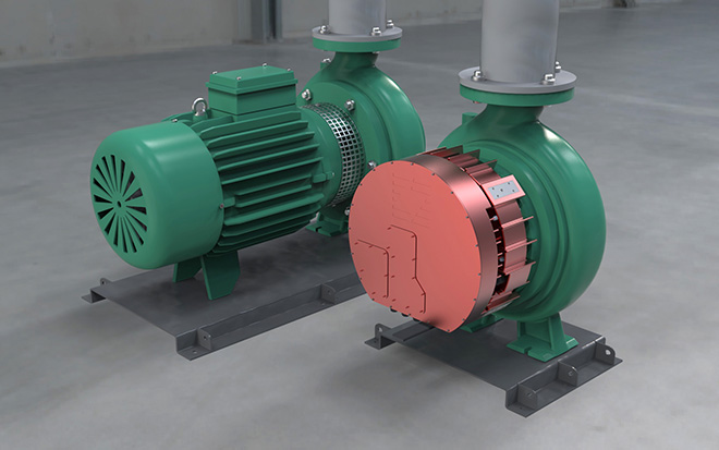
Bhavnesh Patel: Absolutely. We’re in production. We got our first products UL-certified in 2021. We’re selling into industrial applications ranging from fans to pumps, and starting to enter material handling as well. That’s an Infinitum-branded product that we’re selling directly to companies making fans, pumps, conveyor systems, and other industrial applications. Caterpillar Venture Capital also recently invested in Infinitum Electric to develop a new line of smaller, lighter, quieter and more efficient alternators. Our alternators are expected to be one third the size and weight of traditional alternators. We’re targeting the growing $17-billion annual alternator market.

Being able to take what would typically be a 300-pound, couple-hundred-kilowatt alternator and make it a third the size and weight is very attractive, as it potentially reduces shipping and handling costs, material costs, and provides more efficient power generation.

Charged: So, would you say the main benefit to your customers would be weight reduction, and thereby cost reduction?

Bhavnesh Patel: Yes, weight reduction and cost reduction are key benefits, but I’d also add noise, vibration, reliability, and efficiency gains, which equates to extended vehicle range.

Charged: How does Infinitum Electric’s PCB design, prototyping and production process compare to traditional stator manufacturing methods?

Bhavnesh Patel: The process from idea to prototype and eventual commercialization is very different for our technology as compared to conventional motors. The first step is gathering basic application requirements, such as the power, speed, voltage, physical constraints, etc. We input these details into our automated design tool called AutoFlux, which produces dozens of options within minutes. Our electromagnetic engineers then filter out the most promising designs based on the client’s objectives (i.e. highest efficiency, lowest weight, or lowest cost). With input from our client, we’ll narrow down the list to a handful of promising designs and send the Gerber file to one of our PCB manufacturers (Gerber is the equivalent of CAD but for circuit design). Within a few days, we can have a new stator produced and ready for testing. The simplicity of the rest of our motor enables us to complete the prototyping and testing process in a fraction of the time. 

Once prototyping is complete, serial production can be scaled up with limited capital investment. The PCB can be sourced from almost any region of the world, and the rest of the components require simple casting or machining processes. 

Charged: Do you use the same magnet configurations as a standard axial flux motor, or is it something different?

Bhavnesh Patel: It’s a pretty standard magnet material and magnet configuration. The dimensions and the layout are fairly simple. There’s not a whole lot of complexity in terms of the shape of the magnets. If you look at some of the well-known EV manufacturers out there that use magnets in their motors, it’s a fairly complex geometry and a fairly complex process of placing those magnets into the rotor. Our approach is very simple. We have an automated machine that essentially slots magnets onto the rotor, and that’s it. 

The coefficient of expansion of the FR4 and the copper are almost equal, so the whole board expands and contracts at an equal rate, and you never ever have wires rubbing against each other.

Charged: One of the failure points of a standard motor is that the insulation and the windings will break down. Tell me a bit about the insulation of your stators.

Bhavnesh Patel: You’re exactly right—one of the failure modes on a traditional motor is the copper wire windings eventually failing. On wound stators, you’re taking copper wire, you’re bending it over and over, then you’re running current through that, so you’re heating it up and cooling it down over and over again. Over time with expansion and contraction, these wires rub against each other and they eventually break. The other source of failure is the insulation which sits between the copper windings and iron. The copper and iron have slightly different expansion rates, which causes the insulation to fail over time. 

The variability in the conventional stator manufacturing process introduces hotspots that create additional potential failure points. Our PCB stators, on the other hand, are made on a fully automated piece of equipment. You don’t have any of that variability that you typically see on an iron-core stator. As the stator heats up and cools down, the coefficient of expansion of the FR4 [laminate material used to make PCBs] and the copper are almost equal, so the whole board expands and contracts at an equal rate, and you never ever have wires rubbing against each other. There’s no possibility of that happening because of the way the windings are laid out.

We’ve eliminated two of the most common sources of failure. The next most common source of failure is the bearings. Any time you have an inverter-driven motor, it generates bearing currents, and these currents cause the bearings to prematurely fail. Motors typically use more costly ceramic bearings, or they have these grounding rings to mitigate this issue. 

Charged: What about the standard lifetime of the PCBs? What fails on them if they do fail?

Bhavnesh Patel:There was extensive testing done on a three-megawatt motor for a wind turbine application, and they found that the PCB stator was about nine times more reliable than a conventional iron-core stator. 

The main failure points are typically manufacturing defects. In some cases on any PCB production line, you might get voids in the board. The other possibility is vias, which are the interconnects between the layers, failing. The good thing is that all of those issues tend to be identified during the production process because there’s automated inspection equipment that can identify those defects prior to full production being completed. And PCBs have been around for a long time, so the process of quality assurance is robust. 

Charged: Is there anything else on the circuit board? Do you have sensors and other circuits in there?

Bhavnesh Patel: Yeah, absolutely. Because we’re using the circuit board, it’s a lot easier to embed chips and sensors. We typically embed a temperature sensor and an accelerometer on the stator, so we’re able to detect the vibration and temperature of the interior of the motor. This allows us to determine the health of the motor, and also the driven equipment. For example, in a pump application, if you have a blockage in the pump, you might see that on the vibration of the accelerometer before you actually see that physically. In relation to EVs, you might see unusual operating vibration on your motor before you would actually see it in a real-life catastrophic failure.

Charged: Do you develop the power electronics as well?

Bhavnesh Patel:Yes, we’ve developed power electronics, both IGBT and silicon carbide MOSFET-based. We generally prefer the silicon carbide—it’s more efficient—so that’s generally been what we’ve led with, both on the industrial side and the EV side. Some of the partners we’re working with within the transportation segment have their own power electronic platforms that they prefer to use. We’re amenable to using their platform if they want, but we have our own as well.  

This article appeared in Issue 58 – Nov/Dec 2021 – Subscribe now.

from Charged EVs https://ift.tt/sH6nZ5N

Daimler Truck forms joint venture to deploy US commercial charging network


Daimler Truck North America, NextEra Energy Resources and BlackRock Renewable Power plan to form a joint venture to deploy a nationwide US charging network for medium- and heavy-duty battery-electric and fuel cell vehicles. Construction at the first sites is set to begin in 2023. Initial funding is expected to be around $650 million, divided equally among the three parties.

NextEra Energy Resources is an investor in electric infrastructure, and has experience with renewable energy and grid integration. BlackRock Renewable Power operates a renewable energy investment platform that includes investments in over 350 wind and solar projects in 15 countries.

This planned JV is the latest of many partnerships between Daimler Trucks and “top-tier players” in the infrastructure field, including Shell, bp, TotalEnergies, Siemens, ENGIE and EVBox, as well as Traton and Volvo, with which Daimler is working to build a charging network for commercial EVs in Europe.

Daimler sees the lack of a publicly available, nationwide charging infrastructure for commercial vehicles as one of the biggest barriers to widespread deployment of electric trucks. The company and its partners plan to build a network of charging sites on major freight routes along the east and west coasts and in Texas by 2026, leveraging existing infrastructure and amenities while adding greenfield sites to fulfill anticipated customer demand. The initial focus will be on charging stations for battery-electric medium- and heavy-duty vehicles, followed by hydrogen fueling stations for fuel cell trucks. The sites will also be available for light-duty vehicles.

“The planned joint venture with NextEra Energy Resources and BlackRock is another building block in our global partnership strategy to accelerate the infrastructure required for carbon-neutral commercial transportation,” said Daimler Truck CEO Martin Daum. “Whether in the US or in Europe, these collaborations are essential to successfully tackle the urgent need for zero-emission vehicles.”

Source: Daimler Truck


from Charged EVs https://ift.tt/xaOo4I5

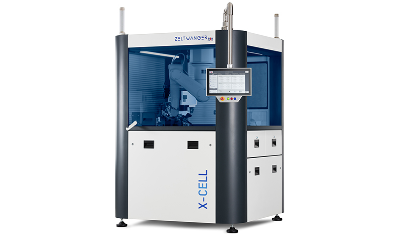
ZELTWANGER’s new laser welding system for EV motor hairpins


Laser and automation company ZELTWANGER plans to introduce a fully-automated laser welding system intended for use in EV motor production.

The system includes a blue-wavelength laser for welding copper and a proprietary clamping system for joining hairpin windings. Copper is a highly reflective element, which poses challenges for welding the stuff. ZELTWANGER says its blue-wavelength laser meets this challenge by providing a simpler and more reproducible welding process. The company also says that, in comparison to previous infrared lasers, its blue-wavelength laser reduces the level of copper pin stripping.

According to the company, the clamping system’s advantages include adjustability for different stator designs as well as lower insulation and space requirements for welding, which contribute to smaller motor dimensions and increased design freedom for motor design engineers.

The system can be tailored to different applications, ranging from prototypes to mass production, and from manual loading to full integration in an automated production line.

Source: ZELTWANGER


from Charged EVs https://ift.tt/oTr8UE7

Tuesday, February 15, 2022

InnovationLab’s new battery monitoring system gathers cell-level data


Printed electronics company InnovationLab has announced a new battery monitoring solution for EVs called BaMoS.

BaMoS is composed of sensor foils, electronics and software. The ultra-thin printed sensor foils measure cell-level pressure and temperature in batteries. The pressure sensors are placed between battery cells, and measure state of charge, identify unusual behavior and prevent overcharging. The electronics component gathers and processes the data. The solution also includes software which provides live visualization, storage and analysis of the data. The size, resolution and substrate material of BaMoS can be adjusted according to customer preferences.

According to InnovationLab, the ability to collect cell-level data can increase battery lifetime by up to 40%, and the new technology would help manufacturers extend the range of EVs by improving battery R&D.

“Measurement is the first step that leads to improved control and battery performance. Our flexible, ultra-thin printed sensors provide the detailed, accurate data that is necessary to improve the performance and lifetime of batteries for electric vehicles,” says InnovationLab Managing Director Luat Nguyen.

Source: InnovationLab


from Charged EVs https://ift.tt/ljnvRVT

Chalmers researchers model reconfigurable EV battery packs that bypass weak cells

Researchers at Chalmers University of Technology in Sweden have assessed how much reconfigurable battery packs could extend EV battery lif...