
One of the primary issues the power electronics engineer must address is the removal of waste heat—the well-known Arrhenius equation from chemistry/physics tells us that the operational life of any given electronic component will roughly double for every 10-11° C drop in its temperature. Power electronics devices on EVs are also under considerable pressure to take up as little volume and mass as possible…oh, and to cost less and less over time. While optimizing all of these metrics simultaneously is rather difficult (invoking that favorite saying of general contractors: good, fast or cheap—pick any two), advanced components and methods for removing waste heat can at least reduce the volume and temperature rise (note that reducing costs is conspicuously absent from the list of potential benefits).
Methods of cooling can be broadly categorized as active or passive. The essential difference is that active cooling uses additional energy (usually electrical) to increase the rate of heat transfer. For example, merely blowing air at a speed of a few meters/second across the fins of an aluminum heatsink can easily double the amount of heat it can dissipate for a given temperature rise, while an even more dramatic increase can be had by pumping a liquid coolant past the heat-generating components (aka a cold plate). While fan cooling definitely falls into the less-expensive end of the active cooling methods, two major downsides to it are the inevitable buildup of dust and dirt on the fan blades and fins (or on the filter placed in front of such), and the higher susceptibility to failure from shock/vibration.
Power electronics devices on EVs are also under considerable pressure to take up as little volume and mass as possible…oh, and to cost less and less over time.
Liquid cooling is altogether more preferable here, as it can achieve exceptionally low thermal resistance values—pretty much only bested by refrigerant-based heat pumps—and liquid pumps tend to survive higher levels of shock and vibration than fans. That said, a fan is often required on the exhaust side of a liquid-cooling loop anyway, so this might be a proverbial case of a distinction without a difference.
The parameters that most strongly influence whether something more involved than a finned aluminum heatsink or cold plate will be required for component cooling are (obviously) the amount of heat, in watts, that needs to be removed, and (rather less obviously) the area over which that heat is concentrated (aka the heat flux, typically specified in units of W/mm2). As component package sizes shrink, there needs to be either a proportional reduction in losses (i.e. an improvement in efficiency) or a reduction in the thermal resistance between the package and the ambient.
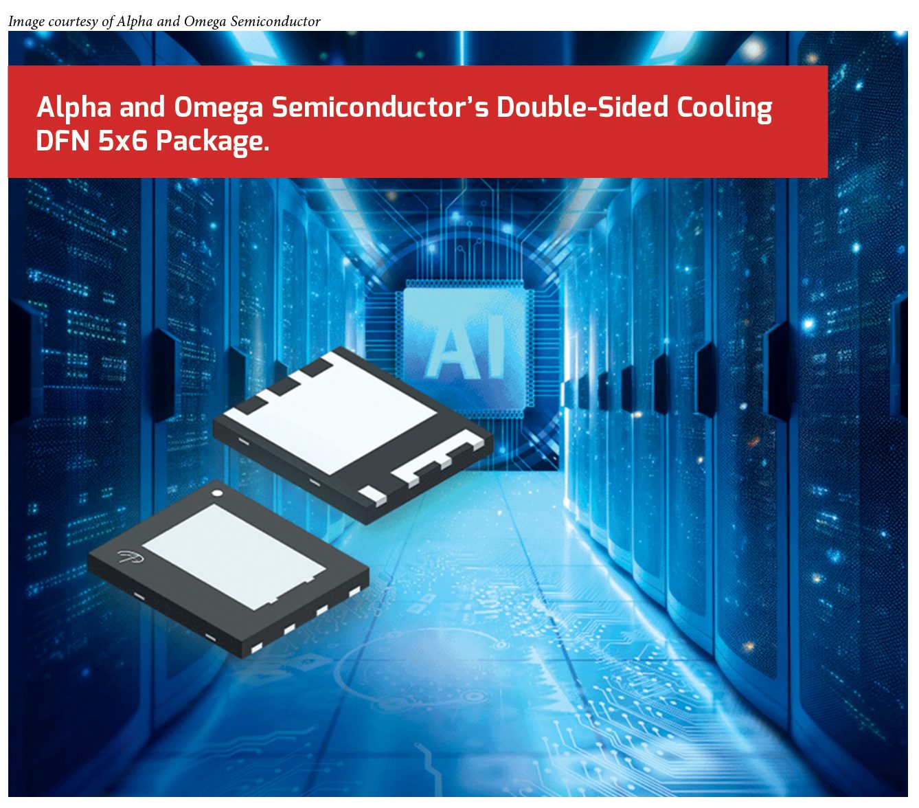
While an improvement in efficiency is always welcome—assuming it isn’t accompanied by an outsized increase in price, anyway—reducing the thermal resistance of the package is more often the most practical solution, and one very simple way for a component manufacturer to do that is to simply make both the top and the bottom of the package thermally conductive (see, for example, Alpha & Omega Semiconductor’s DFN5X6 package). This doubles the surface area available for removing heat from the package without (much of) an increase in the manufacturing cost (for the component manufacturer, anyway—double-sided cooling can be a real headache to implement in the real world without making the device too labor-intensive to economically assemble).
While double-sided cooling is a relatively recent innovation for surface-mount devices, it was extremely popular back in the 1970s and 80s with the so-called “hockey puck” packages used for semiconductor switches and rectifiers. Similar challenges with using those packages back then also apply today, albeit at a much smaller physical scale. One of the biggest such challenges is that one or both heatsink surfaces are likely to be electrically live, so they will require isolation between the components and/or the heatsink (especially if the latter is exposed).
Reducing the thermal resistance of the package is more often the most practical solution, and one very simple way for a component manufacturer to do that is to simply make both the top and the bottom of the package thermally conductive
Another challenge: if multiple components are needed to achieve the necessary power rating, then ensuring coplanarity among them can be a real headache. Also note that, even if the component thickness is tightly constrained, there will still be variations in the thickness of the solder and board. Care must also be used during assembly to ensure that the packages aren’t crushed by excessive clamping force, but that’s standard operating procedure these days. At any rate, the solution to both issues is often the same: an electrically-insulating thermal interface material. The ubiquitous Sil-Pad comes to mind, but a recent innovation—using so-called “phase-change materials”—will be discussed below.
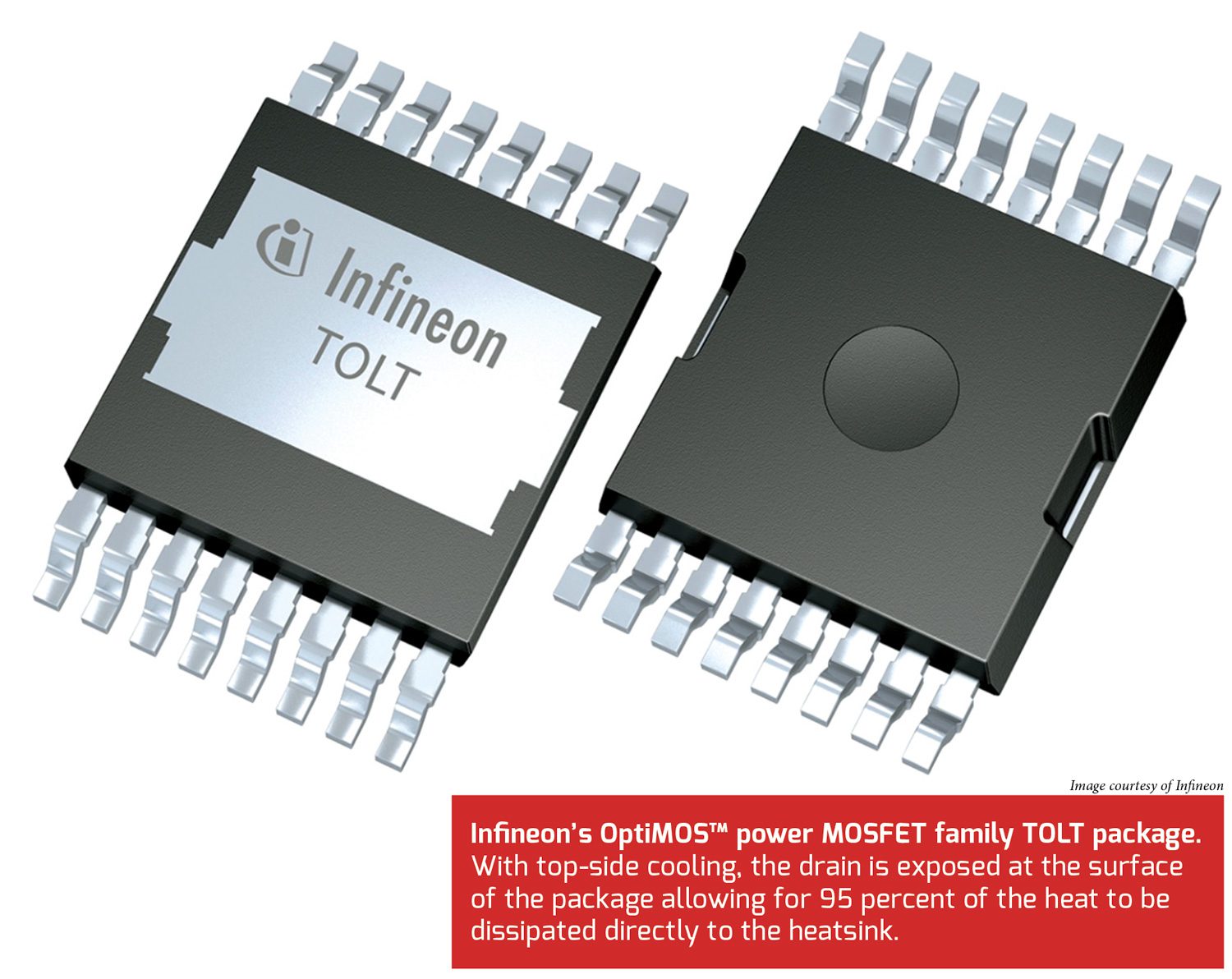
Another recent innovation: semiconductor packages with their heatsink-contacting surface facing up, rather than the printed circuit board (such as the TOLT package from Infineon). This enables a reasonably high power dissipation (or Pd) rating without requiring the oft-specified (and frankly unrealistic) 25 mm x 25 mm pad to even get 1 W of Pd out of an SMT package. The same issue of ensuring coplanarity among an array of the same packages and their attendant heatsink (or cold plate) applies here, with the added caution that it is rarely possible (and always inadvisable) to use the PCB as the other side of a clamp. The usual solution to this issue is to bond the packages to their heatsink/cold plate with a thermally-conductive adhesive or epoxy. These adhesives contain fine particles of copper, aluminum or graphite, which improves their thermal conductivity over conventional adhesives (and definitely the air gap they are meant to displace), but be that as it may, their thermal conductivity will still be far worse than almost every other thermal interface material, and they do render the board more or less non-repairable.
A key enabling technology for the new SMT packages mentioned above is the use of thermal interface materials, or TIMs, which undergo a physical state change (e.g. from solid to liquid) upon rising above a critical temperature.
A solution that preserves repairability is to stiffen the PCB with metal plates or bars on the underside of the board, so that the heatsink mounted on top clamps against these fixtures instead of the board itself. Regardless of the component packaging chosen, more than usual care must be exercised in balancing the mass of the heatsink assembly against the flexibility of the PCB when mounting everything—it may be found that rigidly attaching the heatsink to the enclosure and letting the PCB float is the most reliable option when the heatsink greatly out-masses the PCB.
A key enabling technology for the new SMT packages mentioned above is the use of thermal interface materials, or TIMs, which undergo a physical state change (e.g. from solid to liquid) upon rising above a critical temperature (no prizes for guessing their abbreviation is PC-TIM). This results in a much more thorough displacement of any air trapped between the package(s) and heatsink, which greatly reduces the effective thermal resistance of this juncture, and it also better accommodates any slight differences in height/thickness across multiple coplanar packages.
Current generation PC-TIMs have a thermal resistance on par with silicone greases but are much more resistant to “pump-out,” which happens when the TIM is squeezed out of the interface from thermal cycling, resulting in a gradual—and usually fatal—increase in the thermal resistance of the interface. PC-TIMs do cost more than conventional TIMs, but the improvement in thermal resistance and greater ease of application—they typically come in preformed pads, much like the aforementioned Sil-Pads, for example—more than make up for their higher cost in all but the most cost-sensitive of applications.
Another application in which material sciences has made some impressive strides is the humble heatsink itself. Replacing metals such as aluminum or copper with polycrystalline ceramics comprised of aluminum oxide (alumina, or Al2O3) or aluminum nitride (AlN) powders allows a heatsink to be molded into any practical shape, then fired at high temperature, more or less like pottery. These ceramics are excellent electrical insulators (>10 kV/mm of thickness), as is to be expected, but also good thermal conductors, which is rather more surprising, because good electrical insulators are usually good thermal insulators, too.
In fact, the thermal conductivity of polycrystalline AlN can rival that of metallic aluminum (150-200 W/m * K), while Al2O3 delivers a rather more modest—but still useful—thermal conductivity in the range of 20-40 W/m * K. The coefficients of thermal expansion of both these ceramics are also a good match for most semiconductor materials, so it is possible to directly attach semiconductor dies to them. However, these alternative heatsink materials are not cheap (especially AlN), and they are both quite brittle and very difficult to machine (and note that some machining or grinding after they are fired will be required to achieve the necessary flatness and roughness for a good thermal interface).
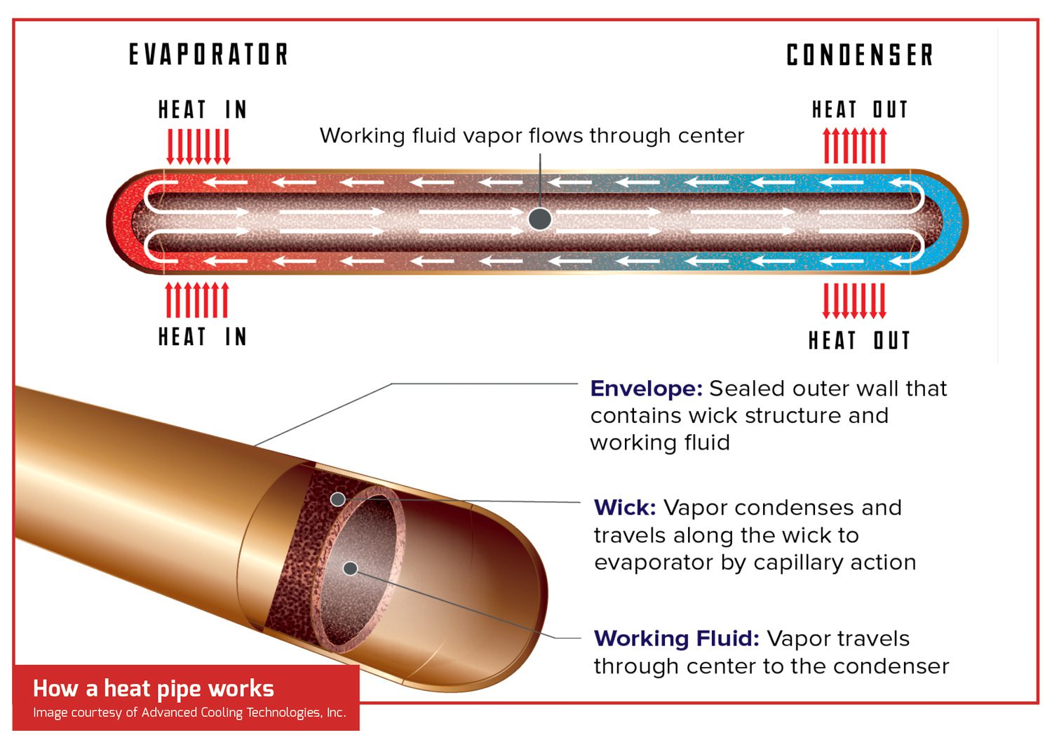
The last advanced cooling method to consider is the use of heat pipes, which are effectively passive heat pumps in that they use the very heat energy they are transporting to do said transporting. A typical heat pipe consists of a sealed copper tube which is charged with a small amount of a liquid that boils in the range of 60-80° C (i.e. higher than the highest expected ambient temperature, but low enough for the component being cooled to survive) and whose interior is lined with sintered copper particles (roughly the size of fine sand) which act as a wick to transport this liquid via capillary action. When one end of a heat pipe is in contact with a hot surface while the other end is exposed to the cooler ambient, then the internal liquid will begin to evaporate at the hot end, absorbing considerable heat energy in the process from the so-called latent heat of evaporation.
The last advanced cooling method to consider is the use of heat pipes, which are effectively passive heat pumps in that they use the very heat energy they are transporting to do said transporting.
As the vapor finds its way to the cool end it will then release much of its heat energy as it condenses, at which point the capillary action of the wick will return said liquid to the hot end. Water is the most commonly used liquid in heat pipes because it has a very high latent heat of evaporation, but the interior of the heat pipe must be at a lower pressure than the atmosphere (i.e. a partial vacuum) to lower its boiling point. This inevitably makes a heat pipe with water as its transport medium more expensive to manufacture, but the payoff is an effective thermal conductivity that can reach as high as 100 kW/m * K, or around 500 times greater than that of 6061 aluminum alloy (approximately 200 W/m * K) or nearly 300 times greater than pure C110 copper (350-400 W/m * K).
This extremely high thermal conductivity makes it possible to more densely package a number of components together and then move the heat they produce to a conventional aluminum heatsink, without needing fans, pumped liquids or other means of active heat transport to lower the thermal resistance of the heatsink. A heat pipe-based cooling system is likely to be much more compact and more reliable, and it will also require far less (practically zero) maintenance. If this prose about heat pipes is not enough to convince the more skeptical among you, then pick up a heat pipe from an online retailer and hold onto one end with your bare hands while pressing the other end into an ice cube. The heat pipe will cut through the ice cube surprisingly quickly…for as long as your hand can withstand the relentless freezing cold that will be conducted back to it, anyway.
This article first appeared in Issue 72: April-June 2025 – Subscribe now.
from Charged EVs https://ift.tt/ktVzD1A


No comments:
Post a Comment